Modifications portfolio
Our work
List of modifications
Helicopters / Airbus / AS365N/N2/N3/EC155B1
MAP039 – Centre Console Reconfiguration
MAP042 – 3rd ICS Jack
MAP043 – Flight Data Management – Quick Access Recorder Installation
MAP047 / MAP065 – Fire Extinguisher Relocation in Cabin
MAP051 – Helicopter Emergency Egress Lighting (HEEL) System Installation
MAP052 – Cockpit Voice Recorder Replacement
MAP061/MAP085 – HF removal
MAP062 – Skytrac ISAT-200 SATCOM Installation
MAP073-MAP079, Flight Manual Supplements - Translations
MAP079 – HR Smith ADELT CPI Installation
MAP080 – Replacement of KXP 756 transponder with Garmin GTX330 Mode-S Transponder
MAP083/MAP086/MAP152/MAP153 – Replacement of VHF radios with 8.33kHz capable radio systems, Fleet standardisation
MAP084 – Axnes PNG installation
MAP100 – FLIR 2000 integration on AS365N2
MAP105 – TAS installation
MAP108 – Passenger intercom extension
MAP148 – Partial Air Conditioner removal
MAP150 – Shock Mounts Replacement RNAV ARINC Tray
MAP155 – External Paint Livery
MAP156 - USB Power outlets in instrument panel
MAP158 - Flightcell DZMx installaiton
MAP159 - COBHAM (NAT) NPX-138 VHF FM Installation
MAP162 - Jupiter Avionics Headset Expander Installation
MAP163 – 28VDC power outlet change in cabin
MAP165 - ICS Channel switching
MAP170 - Tail fin cover modification for a VHF FM antenna
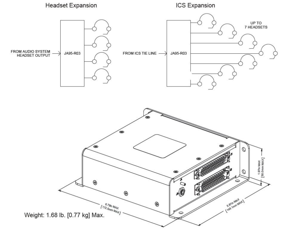
MAP162 - Jupiter Avionics Headset Expander Installation
An ICS headset expander system (JA95-R03) from Jupiter Avionics, a Canadian equipment manufacturer has been installed to increase the capability of the ICS system.
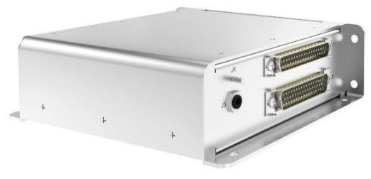
The intended application of the system is to expand one headset connection point to four, enabling further headsets to be connected. The system will enable PTT but not VOX for the headsets connected through the system. Neither PTT nor VOX will however be utilised in the design, as the design will follow current design principles as other ICS jack in the cabin. The newly introduced ICS jacks are distributed in the cabin passenger compartment ceiling in locations suitable for the envisaged operation.
The modification includes (customer documents):
- Mechanical installation drawings
- Wiring diagrams, including routing
- Engineering orders
- Instruction for Continued Airworthiness
- Flight Manual Supplement
To request development and/or EASA approval of a modification or repair, please contact us.
CONTACT US
EASA Design Organisation approval
Certified design
MAP 21 achieved an EASA Part 21 Subpart J Design Organisation Approval in 2007, EASA.21J.326, which enables us to approve modifications to the aviation industry as a delegated EASA authority.