Modifications portfolio
Our work
List of modifications
Helicopters / Airbus / AS365N/N2/N3/EC155B1
MAP039 – Centre Console Reconfiguration
MAP042 – 3rd ICS Jack
MAP043 – Flight Data Management – Quick Access Recorder Installation
MAP047 / MAP065 – Fire Extinguisher Relocation in Cabin
MAP051 – Helicopter Emergency Egress Lighting (HEEL) System Installation
MAP052 – Cockpit Voice Recorder Replacement
MAP061/MAP085 – HF removal
MAP062 – Skytrac ISAT-200 SATCOM Installation
MAP073-MAP079, Flight Manual Supplements - Translations
MAP079 – HR Smith ADELT CPI Installation
MAP080 – Replacement of KXP 756 transponder with Garmin GTX330 Mode-S Transponder
MAP083/MAP086/MAP152/MAP153 – Replacement of VHF radios with 8.33kHz capable radio systems, Fleet standardisation
MAP084 – Axnes PNG installation
MAP100 – FLIR 2000 integration on AS365N2
MAP105 – TAS installation
MAP108 – Passenger intercom extension
MAP148 – Partial Air Conditioner removal
MAP150 – Shock Mounts Replacement RNAV ARINC Tray
MAP155 – External Paint Livery
MAP156 - USB Power outlets in instrument panel
MAP158 - Flightcell DZMx installaiton
MAP159 - COBHAM (NAT) NPX-138 VHF FM Installation
MAP162 - Jupiter Avionics Headset Expander Installation
MAP163 – 28VDC power outlet change in cabin
MAP165 - ICS Channel switching
MAP170 - Tail fin cover modification for a VHF FM antenna
MAP084 – Axnes PNG installation
The modification is limited to the installation of the newly developed Axnes PNG system as a wireless extension to the existing Aircraft Intercom System. The aircraft installation part of the Axnes PNG is comprised of a Base Station (BS), Control Panel (CP) and an external antenna. The interface with aircraft systems is limited to:
- Main Bus Bar for 28 VDC power supply via a Circuit Breaker (C/B).
- ICS via a standard analogue connection for exchange of Audio, PTT and VOX. The audio input from Axnes PNG to the ICS will be wired through an additional mechanical switch that will allow the input to be distributed alternatively to one of two separate inputs in the ICS to facilitate separation of the communication between different crew members.
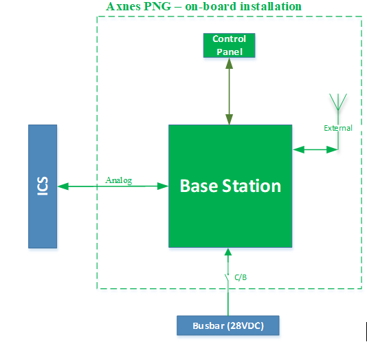
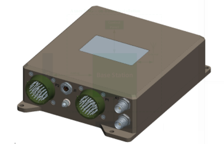
The BS is the central processing unit and will be installed on the AFT cargo bulkhead. The BS requires no HMI (no display or control functionality on the unit). The unit supports both analogue and digital ICS inputs/outputs.
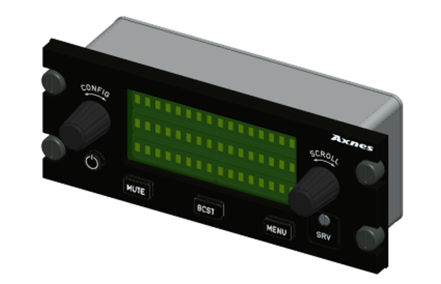
The CP is the PNG’s User Interface. It features a monochrome display which provides status information (e.g. quality of the radio line, configuration parameters, etc.), as well as a menu structure for access to user settings and adjustments. The interaction with the system is achieved through the rotary knobs and discrete switches on the panel. The CP will be installed on the FWD side of the cargo bulkhead on a purpose made attachment bracket, next to one existing passenger seat. The CP is only interconnected with the BS and requires no external power supply.
The antenna to be installed is a standard Cobham Comant CI 273 UHF Antenna.

To request development and/or EASA approval of a modification or repair, please contact us.
CONTACT US
EASA Design Organisation approval
Certified design
MAP 21 achieved an EASA Part 21 Subpart J Design Organisation Approval in 2007, EASA.21J.326, which enables us to approve modifications to the aviation industry as a delegated EASA authority.